
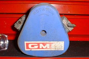
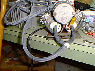
 | My 1973 GMC originally came with a single cylinder Brown compressor, but that had been replaced by a previous owner. The compressor wasn't very strong when I bought my coach and after a long period of storage, it ceased moving air entirely. Since the entire air suspension system was in pretty sorry shape, I figured that the extended run time required for the compressor to keep up with all the leaks had worn it out. That was at least partially true. |
| On later model coaches, a length of vacuum hose connects the two inlet ports and runs through the firewall in order to draw "clean" air from inside the coach. This was not installed on my coach and the mud wasps took advantage of the situation. Now I know why the compressor quit entirely after storage. | 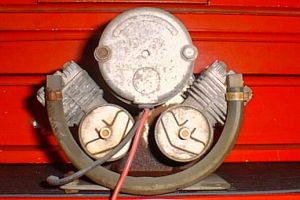 |
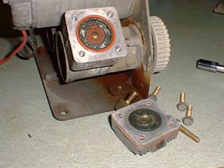
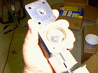
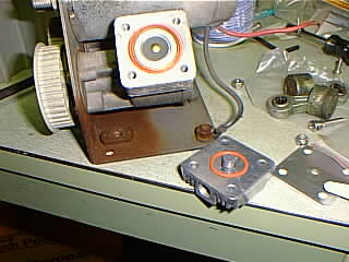
 | The first disassembly step is to remove the two spring clips that hold the plastic inlet ports in place. Be carefull not to lose the little "O"-ring that seals the port to the cylinder housing. Then open up the crimp clamps holding the cross-over hose in place and remove. |
| Then the front cover comes off to reveal the belt and pullies. Carefully remove the belt from the three pullies. Timing the compressor is simple, so there's no need to worry about indexing the belt and pullies. | 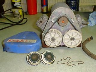 |
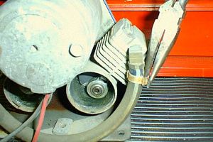
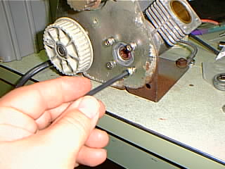
 | Removing the four small bolts on each side allows the cylinder heads to come off. |
| The rod end is held by an "Allen" head stud. The threads are "Loctited", making removal difficult. I tried several different methods of holding the crank eccentric, but finally settled on using some long nose "Vise Grip" pliers to hold it and then draw filed out the marks later. I understand that Ragusa Pattern Shop sells a tool to hold the cranks in place. You don't need to worry about messing up the pistons as the Gateway kit includes new ones. The same goes for the crank shaft. It's also "Loctited". I held the eccentric with "Vise Grip" pliers and turned the pulley with my hand. | 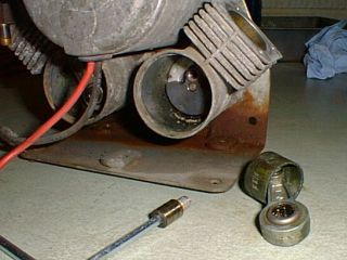 |
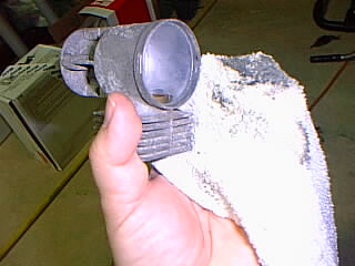
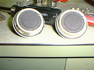
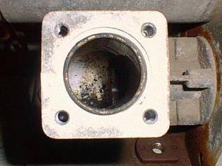 | The cylinder bores are in pretty good shape, but there's a lot of trash in the bottom of the cylinders. The foam "filters" in the inlet ports were decomposing, and since the air was being drawn from the engine compartment, I wasn't very surprised by this. The debris looks like a combination of bits of foam, old grease(from the rod bearings) and dirt. |
| After the crankshaft is pulled out, the cylinder housing is removed by taking out the four bolts behind the pulley. This step is not necessary, but I chose to take the cylinders off to clean all the debris out a little easier. Be careful not to lose the two hexagon shaped plastic "seals" on the crankshaft bearings. You can see the outer one here and there is an identical one on the inside of the crank bearing. | 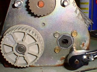 |
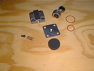 | Here are the parts included in the Gateway rebuild kit. The new design valve plate is in the center and clockwise from the top is the piston assembly, two "O"-rings that seal the valve plate, the foam filter, valve spring and seal and cylinder head. These are the parts for one side - two sets are included. |
| Here's a close-up of one of the old pistons. The ring is worn flat and it is heavily coated with the same gunk that was in the bottom of the cylinder. | 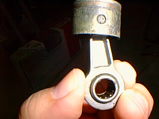 |
 | This cloth was clean when I started. Some mineral spirits, a little swabbing and the cylinder was clean again. I also used a cotton swab dipped in mineral spirits to clean the crank bearings. Then I packed them with Redline CV-2 left over from my front bearing replacement. Note - the instructions warn against lubricating the compressor, but the bearings were contaminated by the same trash that was in the cylinders, so I felt cleaning and repacking was the lesser evil. |
| Here you can see the CV-2 grease. I removed the excess after inserting the crank. Also, since you need to Loctite the threads, I've wrapped them in some masking tape to keep the grease off. Also, I'm about to make a mistake here. The cylinder must be bolted back onto the plate before inserting the crank. | 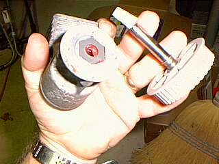 |
 | Here you can see the piston's in place with the lower "O"-ring. The valve plate must be installed with the cone on the piston side. |
| This is the valve and spring before inserting in the center of the head. Note the smaller "O"-ring is installed in the head. | 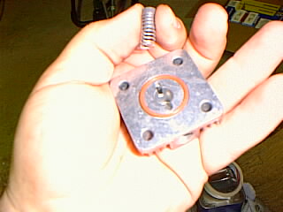 |
 | I replaced the bolts holding the cylinder housing with stainless steel "Allen" head screws. You can see here that I haven't yet replaced the little hex shaped plastic seal. |
| The instructions specify Loctite 242. You don't need much or it will sqeeze out and possibly contaminate the bearings. Just a little in the first couple of threads is plenty. I wiped off the excess after taking this picture. | 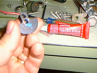 |
 | With the cylinder and piston in place, it's time to install the new cylinder head and valve assembly. Remember, the cone faces the piston. It's a little tricky to keep both "O"-rings in place and start the bolts. |
| After knocking the mud off the inlet ports, I washed them with warm water and dish detergent. Remember to keep the little spring lock that hold the filters in place and clean them up too. | 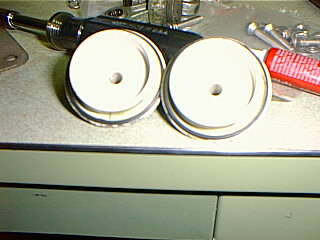 |
 | Now the filters are installed with the spring locks and "O"-rings in place. |
| Almost done. Be careful that the "O"-rings seat properly and the spring clips that hold the inlet ports in place seat in their cutouts. | 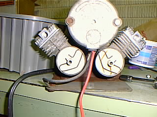 |
 | The fittings off the old heads are reused. Be sure to use Loctite PST and not teflon plumbers tape. The teflon tape gets cut into little strands by the threads and if one of these strands breaks off, it will raise havoc with your compressor and air system. The crossover hose looked to be in good shape, so I cut ½ inch off each end and reused it with small screw clamps. I used 9/32 inch vacuum hose and a 5/16 inch plastic tee for the inlet hose. I'm not going to run the hose inside the coach, but instead I'm going to use a K&N breather filter mounted up behind the front access cover. |
| The rebuild kit is $48.50 and is available from Gateway Motorhome Company at 800-654-0374. Eugene Fisher provided the picture at right of the Ragusa piston tool. The order number is RV-14 ($5.00) from Ragusa Pattern Shop and R. V. Products, Inc. 714-261- 5898. GMCer John Clement, 909-737-0969, has any single part you will need to repair these compressors and he will also rebuild them for you. | 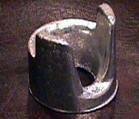 |
member of |
||||
 |
 |
Analysis by |
||